 |
|
|
< Back to Index
 |
|
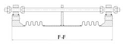
Flanged Universal Expansion Joint |
|
34 inch, 36 inch, 38 inch Nominal Diameter
Notes:
- Rated life cycle at 650°F is 3000 cycles for any one tabulated movement.
- To combine axial, lateral and angular movements, please refer to the how to order section.
- To increase cycle life or movements, please refer to graph on cycle life.
- Rated bellows extension is equal to rated axial movement. Provided bellows is precompressed the amount of design extension. Installed overall length will decrease by the amount of precompression.
- Tabulated values are for tied joints, with butt weld ends. Performance of joints with flanged ends, and unrestrained joints, will exceed tabulated values.
- Maximum test pressure: 1.5 X rated working pressure.
- Bellows rated for 650°F: See catalog flange data for appropriate flange temperature/pressure ratings.
- Pressure thrust load applied to adjacent pipe anchors/equipment when unrestrained expansion joints are used.
|
Size |
Pressure |
Non-concurrant Movements/Spring Rates |
Llateral Movement/Spring Rates |
Axial |
54 |
in.
Overall Length |
66 |
in.
Overall Length |
78 |
in.
Overall Length |
Movement |
Spring Rate |
1372 |
mm
Overall Length |
1676 |
mm
Overall Length |
1981 |
mm
Overall Length |
Movement |
Spring
Rate |
Movement |
Spring
Rate |
Movement |
Spring
Rate |
PSIG |
in. |
lb./in. |
in. |
lb./in. |
in. |
lb./in. |
in. |
lb./in. |
kg/cm2 |
mm |
kg/mm |
mm |
kg/mm |
mm |
kg/mm |
mm |
kg/mm |
34 |
50 |
4.44 |
273 |
6.97 |
129 |
9.56 |
74 |
7.96 |
292 |
3.5 |
113 |
4.9 |
177 |
2.31 |
243 |
1.32 |
202 |
5 |
135 |
2.13 |
1683 |
3.54 |
723 |
5.01 |
398 |
4.5 |
1346 |
9.5 |
54 |
30.1 |
90 |
12.94 |
127 |
7.12 |
114 |
24 |
275 |
1.58 |
4951 |
2.89 |
1856 |
4.25 |
958 |
4.24 |
2699 |
19.3 |
40 |
88.6 |
73 |
33.21 |
108 |
17.14 |
108 |
48 |
36 |
50 |
4.21 |
323 |
6.59 |
152 |
9.05 |
88 |
7.96 |
309 |
3.5 |
107 |
5.8 |
167 |
2.72 |
230 |
1.57 |
202 |
6 |
135 |
2.02 |
1991 |
3.35 |
854 |
4.74 |
471 |
4.49 |
1427 |
9.5 |
51 |
35.6 |
85 |
15.28 |
120 |
8.43 |
114 |
26 |
250 |
1.52 |
5853 |
2.78 |
2194 |
4.09 |
1132 |
4.31 |
2860 |
17.6 |
39 |
104.7 |
71 |
39.26 |
104 |
20.26 |
109 |
51 |
38 |
50 |
3.99 |
379.0 |
6.26 |
179 |
8.59 |
103 |
7.96 |
327 |
3.5 |
101 |
6.8 |
159 |
3.20 |
218 |
1.84 |
202 |
6 |
130 |
1.93 |
2333.0 |
3.21 |
1001 |
4.53 |
552 |
4.52 |
1508 |
9.1 |
49 |
41.8 |
82 |
17.91 |
115 |
9.88 |
115 |
27 |
250 |
1.44 |
6859 |
2.64 |
2571 |
3.88 |
1327 |
4.3 |
3021 |
17.6 |
37 |
122.7 |
67 |
46.01 |
99 |
23.75 |
109 |
54 |
Materials
Bellows: A240-T304. Alternate materials available upon request. Refer to the materials section.
Flanges: ASTM A105.
50 PSIG Series: 125 lb. Lt/Wt FFSO.
For 130-135 PSIG Series and 250-275 PSIG Series: Customer to specify actual flanges required.
Plate flanges and angle flanges available for low pressure systems.
Pipe: ASTM A-285-C.
50 PSIG Series: 0.375-inch wall
130-135 PSIG Series: 0.375-inch wall.
250-275 PSIG Series: 0.500-inch wall.
Liners: A240-T304.
Covers: Carbon steel.
Tie Rods, Hinges, Gimbals: Carbon steel
|