|
|
| |
Often the piping arrangement, force limitations, number of operating cycles, and economics, dictate that deflections may not be simple axial motions as described above, but will be lateral, angular or combinations of all three. The following examples show how various piping problems are solved with different types of pipe expansion joints, anchoring and guiding arrangements.
EXAMPLE 6 |
| |
|
| |
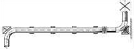
In this example, if the pressure and deflections are low enough, an inexpensive single pipe expansion joint is able to absorb the thermal expansion of both the pipe run in which the pipe expansion joint is located, and the perpendicular pipe. The growth of the perpendicular pipe produces lateral deflection in the pipe expansion joint, while axial deflection absorbs the growth of the horizontal run. This combination of movements is, therefore, handled by a single pipe expansion joint. The pressure thrust cannot be resisted by the pipe expansion joint and a "directional" anchor must be provided at the elbow to permit the elbow to deflect vertically. The pipe guiding required follows that of Example 1.
EXAMPLE 7 |
| |
|
| |
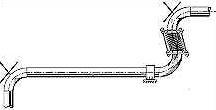
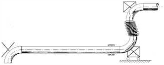
As in Example 6, a single pipe expansion joint absorbs, as lateral deflection, the thermal expansion of the long horizontal pipe run. The benefit of this arrangement is that the anchoring to restrain the pressure thrust is confined to the short pipe leg that contains the pipe expansion joint. The long pipe is in tension from its pressure thrust and does not require extensive guiding. A directional anchor is located at the lower elbow, with the freedom to permit the growth of the horizontal pipe. The upper elbow is attached to a main anchor, and is the fixed point from which all the deflections are calculated. At the left elbow, an intermediate anchor is added to fix the end of the portion of pipe from which the pipe expansion joint is accepting movement.
If lateral deflections will be larger than a single pipe expansion joint can accept, a universal type can be used, as shown below. |
| |
|
| |
EXAMPLE 8 |
| |
|
| |
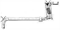
When anchoring to absorb the pressure thrust shown in the previous example is impractical, or uneconomical, an arrangement using a tied single pipe expansion joint can be used as shown above. The tie rods are tension devices which act the same as the pipe wall in resisting or carrying the pressure thrust. As a result, the length of the pipe expansion joint becomes fixed, and the unit cannot absorb the axial deflection produced by the thermal expansion of the pipe in which it is installed. The pipe expansion joint will absorb, as lateral deflection, the thermal expansion of the long horizontal pipe. Since the short vertical pipe length will change due to the rotation of the tie rods and the thermal expansion of it's elbows and hot pipe, the horizontal pipe will bend. Therefore a planer guide is provided as shown. This arrangement will only work if the horizontal pipe can accept the bending. Usually it is practical and economical for small vertical movements and/or long horizontal pipe runs. |
| |
|
| |
As in EXAMPLE 7, if large lateral deflections must be absorbed, tied universal expansion joints should be provided as shown above.
EXAMPLE 9 |
| |
|
| |
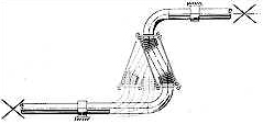
This arrangement is similar to EXAMPLE 8, except that the need for the long horizontal pipe to accept bending is reduced or eliminated, by the attachment of the tie rods from elbow to elbow. Thus, the length of the vertical pipe between the elbows, including the pipe expansion joint, is fixed.
All the thermal expansion of the vertical leg is absorbed by the bellows within the tie rods. Some bending of the long pipe will occur due to the rotation of the tie rods during the lateral deflection. However, since the rods now cover a longer distance, the angle they must rotate for a given lateral deflection is considerably reduced. |
| |
EXAMPLE 10 |
| |
|
| |
The previous examples dealt with all the piping and deflections in a single plane. Often, however, pipe runs change planes as well as direction, and the resulting thermal expansion can appear to be complicated. In this example, a tied universal expansion joint is shown accepting the thermal growth of two horizontal pipes in two different planes. The example is almost identical to Example 8, except that the lateral deflections must be analyzed as vectors. The real deflection of the pipe expansion joint is a single resultant lateral deflection in a single resultant plane. The axial thermal expansion of the pipe length that includes the pipe expansion joint is absorbed within the pipe expansion joint and by bending the pipes just as in Example 8.
The pipe expansion joint can also have the tie rods attached to the elbows, as in Example 9, and achieve the same benefits, but the deflections must still be determined as vectors, as above.
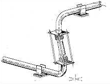
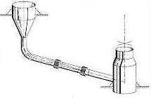
EXAMPLE 11 |
| |
|
| |
In this example two vessels are connected by a straight inclined or horizontal pipe. As shown, each vessel is assumed to be an anchor, wherein the vessel supports must be capable of accepting the pressure thrust developed in the pipe, in the direction of the axis of the pipe. The purpose of the pipe expansion joint is to accept the thermal expansion of the distance between the centerlines of the vessels. Even though the pipe is attached to the right vessel at its wall, the growth of the diameter of the vessel itself adds to the connecting pipe growth. The growth from anchor point to anchor point must be used for the thermal expansion calculation.
Here we have used an untied universal expansion joint, since the growth of the pipe is accepted as axial compression by the bellows. When the pipe is inclined, or the elevation of the anchor of each vessel is different, the vertical thermal expansion creates a lateral deflection vector, which is easily accepted by the universal type of pipe expansion joint.
In this application, because the pipe and expansion joint are horizontal, or inclined, the weight of pipe spool between the bellows must be considered in the final design. Tie rods which do not restrain the thrust or control rods, can be added to suspend the center spool. Similarly, slotted hinges can be added over each bellows. Another mechanism for the same purpose is a pantographic linkage.
The advantage of the pantograph is that it automatically distributes the axial deflection equally between the two bellows without the addition of other devices. |
| |
|
|